
Yes! I never liked typing the letters in the left column, now it’s not possible!
I just copy and paste them from Wikipedia
Where do you copy the A from to get to Wikipedia?
From here: https://en.wikipedia.org/wiki/A?wprov=sfla1
Ahh, but that still needs you to type an A… 3 actually. What’s your real source of A’s huh???
I have it bookmarked for q, a, z on my toolbar. Just had to suffer googles autocorrect once to get the wikipedia page
I only need to start the w and everything lines up in my url bar for me to ‘down arrow, enter’ my way to wikipedia. I only go to three sites anyway, right?
Who needs Q, Z and, erm, A, anyway? Nobody!
How did you even type those characters?!
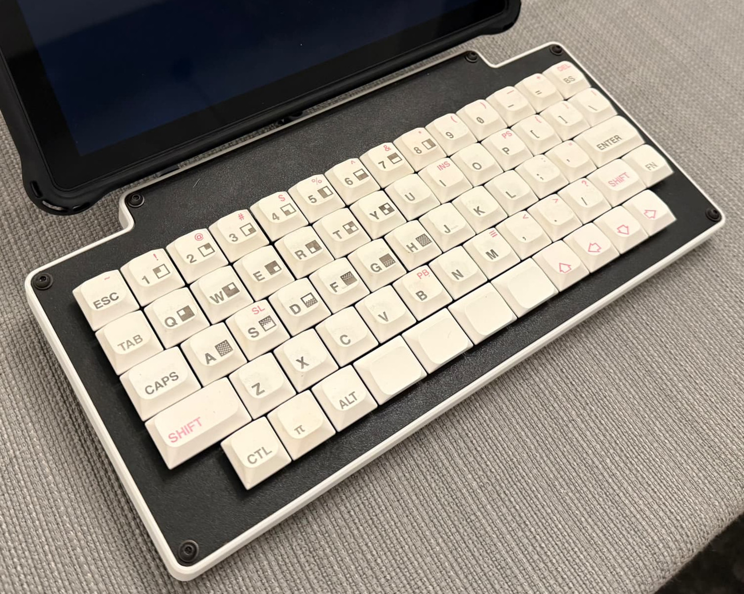
What looks like left sided mods of esc, tab, shift are in fact q, a, z. Esc is q and w together, tab is a and s, shift is if I hold down Z.
Why would I choose to do this? To get me to use my pinkies more for normal typing. On a 40% (which is my normal keyboard) I use only the three larger fingers, which is a bad habit if speed is your aim.
This keyboard has no time for questions.
It’s a good thing it has dual spacebars, or else this board would be seriously flawed.
Indeed, multiple spacebars is what really makes these types of boards work. I like having four of them personally.
You rang?
While a 1u spacebar may sit on the council we will not grant it the rank of master
Then it’s a good thing the gang of four there are all 1.25u!
Which is not to say your decision is anything other than ourageous and unfair. We’ll see what the Supreme Chancellor thinks.
Not the younglings!
Seeing this board again inspired me to revisit my own custom. I really love how even with 14 columns it remains symmetric without using too many odd-sized keycaps (not against using a few blanks for the mods). And the arrow keys! This is the layout I’ve settled on for my own use: https://www.keyboard-layout-editor.com/#/gists/68b440125bd9755baf0fcb5faf19ed61
If it turns out OK I might have to get a case milled.

Very cool!! I think your bottom row may ultimately prove slightly more user friendly than mine, though I certainly got used to it. The ortholinear number row has proven to be a non-issue for me, though I have the “advantage” of not truly touch typing, and my hand-eye coordination therefore doesn’t have too much trouble with losing that 0.5u stagger.
Yeah I never developed the muscle memory for the num row so it shouldn’t be a problem
This is sexy. I need details.
DIY board. I designed a no-stabs matrix-only PCB (the Pi Pico MCU has to serve as the “daughterboard”). It’s FRL 1800 and is one of my personal favorites, though I’ve since replaced the black spacebars with a couple of BOW keys that reflect the hold-tap mapping I set up; I’ve also changed it from KMK to ZMK.
Anyway, PCB orders usually have a minimum order of 5 pieces, so I snapped the numpad off of one and laser-cut a case of sorts, really just plates and spacers, and got “half-height” switches. My laser can sort of half-assedly dye-sub cheap PBT blanks, so I did a Timex Sinclair design. Later, I added feet, a 3D printed replacement one-piece spacer with a sidewall, and a MagSafe ring so it could be the keyboard for a Chrometab I converted to Debian.
You “snapped the numpad off” and the rest of the board kept working?! I wish to subscribe to your blog.

I mean, it helped that I knew the designer, LOL.
IIRC, there is one single bodge wire in there from where I did compromise the matrix, but I cannot stress how simplistic this PCB design was. It is holes for switches, holes for diodes, holes to string it over to the microcontroller dev board, and traces connecting them all. My second one is slightly more ambitious, allowing a couple of layout choices, Alps or MX, and has a designated spot to solder a specific MCU. That one requires two bodge wires because I screwed up the traces a little. If I do a third, I will know to make sure every trace is assigned to a “subnet” before I tell KiCAD to clean things up.
Its for academic purposes, makes double spacing easier
Especially if you’re Python programmer
↑↑↓↓←→←→B…shit
Congrats you’ve unlocked extra hard mode, we removed the backspace and delete keys from all layers
Vim users: i have 73 ways to delete text and those aren’t even my favourite ones.
I have plenty of combo and macro space on the complied hex for this board, so I can just shove those into there and :!unix_command rm -rf -no-preserve-root /
Cute.


